
En
Hard rock gold differs fundamentally from alluvial (placer) gold. The gold is locked inside quartz or sulphide matrix, so liberation through size reduction must come before any gravity or chemical recovery step.
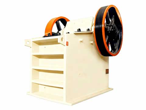
Raw ore is fed from a hopper into a jaw crusher (feed size ≤ 500 mm, discharge ≤ 80 mm). At 50 t/h throughput, a single PE-600×900 jaw crusher running at 220–270 rpm handles the load comfortably, drawing approximately 55 kW.
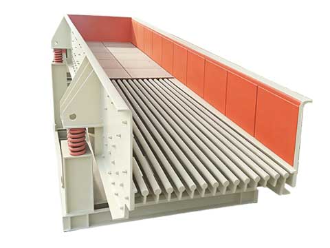
A vibrating grizzly feeder upstream pre-screens fines below 20 mm and routes them directly to the secondary stage, reducing wear on the jaw plates by an estimated 15%.
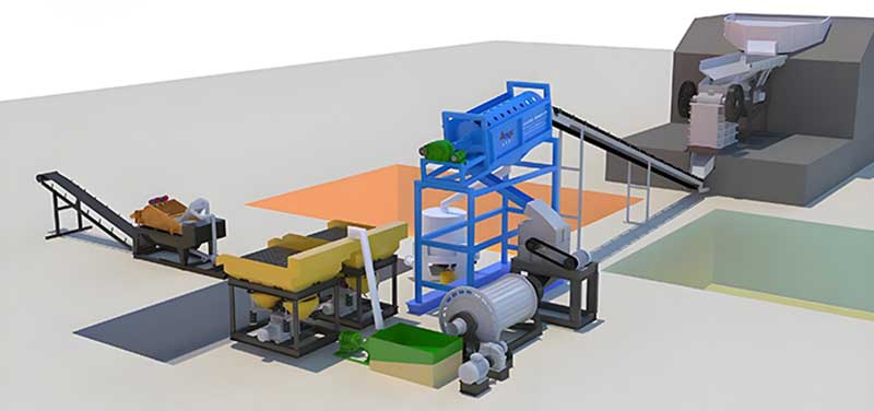
Crushed product from the jaw crusher travels via a belt conveyor to a secondary hammer mill, reducing particle size to ≤ 10 mm. This stage is visible in the flow diagram as the large grey unit at the feed end of the circuit.
The hammer mill rotor speed is set at 980 rpm, producing a uniform 6–10 mm discharge that feeds the grinding mill without creating excessive fines that would overload the classification system.
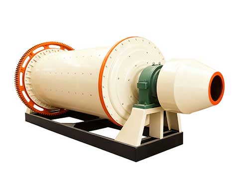
The core liberation stage is a closed-circuit ball mill paired with a spiral classifier the blue elevated structure at the centre of the flow diagram. The ball mill (model MQY-1830×3600, 22 kW) grinds ore in a slurry (water-to-solids ratio 1:1 by weight) to a product fineness of -200 mesh at 75–80%.
Oversize returned from the spiral classifier loops back into the ball mill, ensuring no coarse particles bypass the liberation circuit. This closed loop is critical for hard rock gold: coarse particles retain locked gold that gravity equipment cannot recover.
Ground slurry overflows the classifier and feeds a bank of shaking tables — the yellow inclined units at the left-hand side of the circuit diagram. Shaking tables exploit the density difference between gold (19.3 g/cm³) and gangue silicate minerals (2.65 g/cm³).
Two double-deck shaking tables (2,100 × 1,050 mm deck size) handle the 50 t/h flow. Each table produces three products:
Gravity recovery at this stage captures 55–60% of total gold — the coarser, liberated fraction — without any chemical reagents.
Shaking table concentrate is collected in the green sump visible at the bottom of the flow diagram and pumped to the gold room for final upgrade. Depending on the project’s environmental permit and local regulations, this stage uses either:
For this West Africa project, an ACACIA-type intensive leach reactor was installed, treating the 4–6% concentrate fraction only (not whole-ore leach), which reduces cyanide consumption by over 80% compared to carbon-in-leach circuits.
Process water from the classifier overflow and shaking table discharge is collected in a tailings thickener, where flocculant is added to settle fine solids. Overflow water (>95% clear) is pumped back to the ball mill feed — critical in the semi-arid site to meet the local water allocation limit of 0.3 m³ per tonne of ore processed.
The thickened underflow is pumped to a lined tailings storage facility (TSF) with a leak detection layer.
Three design decisions drove the above-target performance:
A 50 t/h fixed hard rock gold processing plant combining jaw crushing, hammer milling, closed-circuit ball milling, shaking-table gravity concentration, and intensive concentrate leaching delivers reliable >87% gold recovery at a capital cost approximately 40% lower than a full carbon-in-leach circuit of equivalent throughput. The circuit is modular: throughput can be doubled to 100 t/h by paralleling a second ball mill and table bank without redesigning the crushing or leaching sections.
For project enquiries, equipment quotations, or site-specific process design, contact our engineering team with your ore grade, feed tonnage, and site location.